26th May 2023
Last month we commenced manufacture of the fold mirror; so over the last couple of months the team have been preparing the support structures that will hold it in place. This includes the adjustable mount and the testing of potential methods for gluing the support pads to the back surface of the mirror.
Linear stage setup and glue bond testing
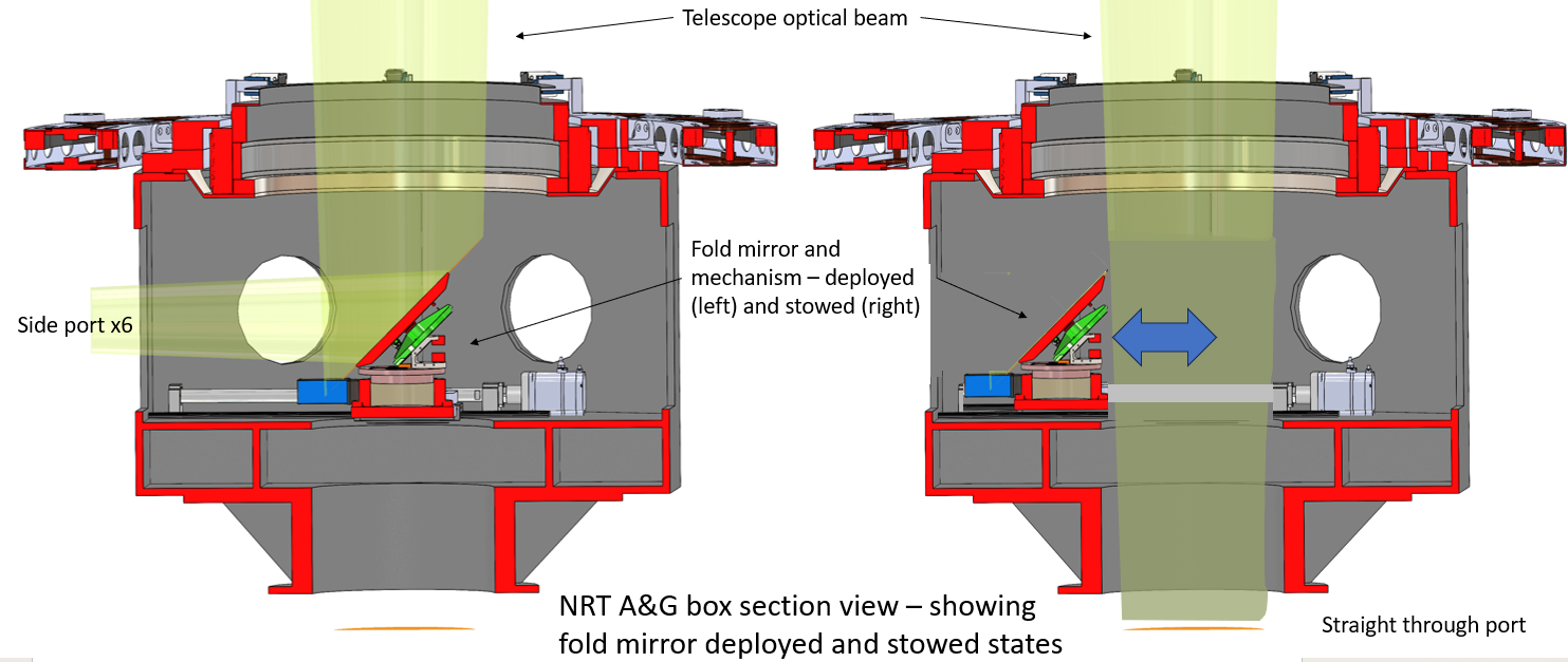
With an upcoming visit from the IAC software team members to LJMU, Adam Garner (control and automation engineer) has been working on the fold mirror linear stage system. The linear stage allows the fold mirror to move into the centre of the acquisition and guidance box (which houses all the instruments) and rotate to reflect the light path to the chosen instrument port. Importantly, the mirror must also move out of the way so that the optical path can to go to the 'straight through' cassegrain instrument port.
Schematic diagram showing the acquisition and guidance box section view with the science fold mirror in deployed and stowed states.
The linear stage is being assembled in the lab at LJMU and consists of a Maxon motor driving a leadscrew mechanism. This enables the fold mirror to clear the optical path and position itself accurately at the centre of the beam when it is in its deployed position. In the lab the control electronics are used to drive the motor so the software can be fully tested before the next phase of integration to the rest of the telescope software stack.
This prototype provided an excellent opportunity to test the glue bonds of the mirror pads to ensure they could withstand the required force. The setup was adjusted using rope and a connection to one of the test pads to allow a tension force to be applied to the glue bond based on the distance of the platform from the sample. A load cell was used in place of the fold mirror to record the force exerted by the linear motor on the pad.
Lab setup at LJMU to demo the linear stage for moving the sciencefold mirror into the optical light path of the telescope.
This setup above shows a monitor with output from the strain guage. This is used to measure the force being applied to the small pad glued to a glass sample (left of image). The moving stage runs along two rails and the force is applied via a rope. The rails and moving platform are very similar to those which will be used in the final design so this setup is very useful to show how the fold mirror linear movement will be controlled. The maxon motor with attached ballscrew mechanism is shown on the right which drives the platform back and forth.
During the test the motor drives the platform away from the pad and glass assembly so the tension in the rope slowly increases. The team plotted the force over time and ultimately the failure limit of the glue bond.