The NRT has an altitude-over-azimuth yoke system mount. The total mass is ~60tonnes made up mostly of welded steel parts. One of the driving science requirements of the telescope structure is the 30 second time-to-target requiring a stiff and light-weight design. The sub-systems making up the structure are:
Telescope mount The mount or ‘forks’ provide the rotating structure that holds the telescope tube. Both azimuth and altitude drive systems are housed within this structure and the mount is fixed to the pier via the azimuth bearing.
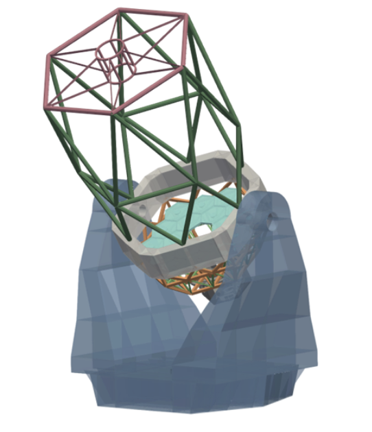
Telescope tube The telescope tube holds the secondary mirror (M2) ~6.6m from the primary mirror (M1) vertex. It is fixed to the mount via trunnion bearings which allow it to rotate and ‘point’ between zenith (straight up) and down to 20degrees above horizon. It is neutrally balanced around it’s bearings to aid stable pointing and reduce required force from the altitude drive motors. The tube is required to move at six degrees/second to support the NRT time-to-target requirement. The centre section is the middle part of the tube which rotates around journal bearings on each side. It also allows mounting of the primary mirror cover which folds down when not observing.
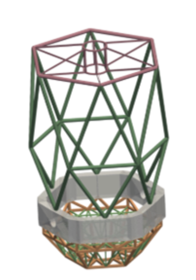
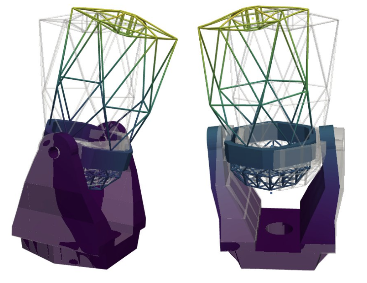
The tube is designed to be very stiff to ensure the M1 and M2 hold their position relative to each other as the tube points up and down (changing gravity angle) and as any wind buffets the tube structure. An additional requirement is for the tube structure to allow removal and replacement of M1 mirror segments for washing and re-coating. The top end ring is at the very top of the tube and includes thin vanes which suspend the M2 system above the M1 mirror. The vanes need to be stiff but thin to reduce obscuration of light hitting the M1.
The M1 cell supports the M1 segments and associated optomechanical supports. This part of the structure is fixed to the lower part of the centre section.
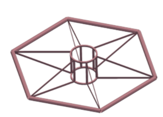
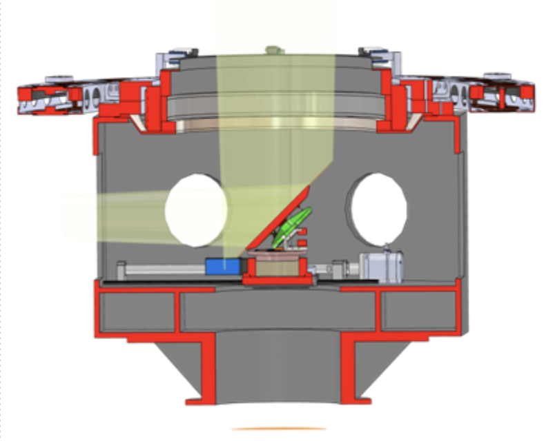
Focal station The focal station is mounted to the bottom of the M1 cell and the whole system rotates around the optical axis to de-rotate the sky image on the instrument detectors. The focal station system is made up of the following elements.
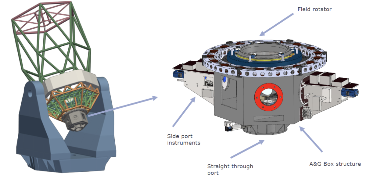
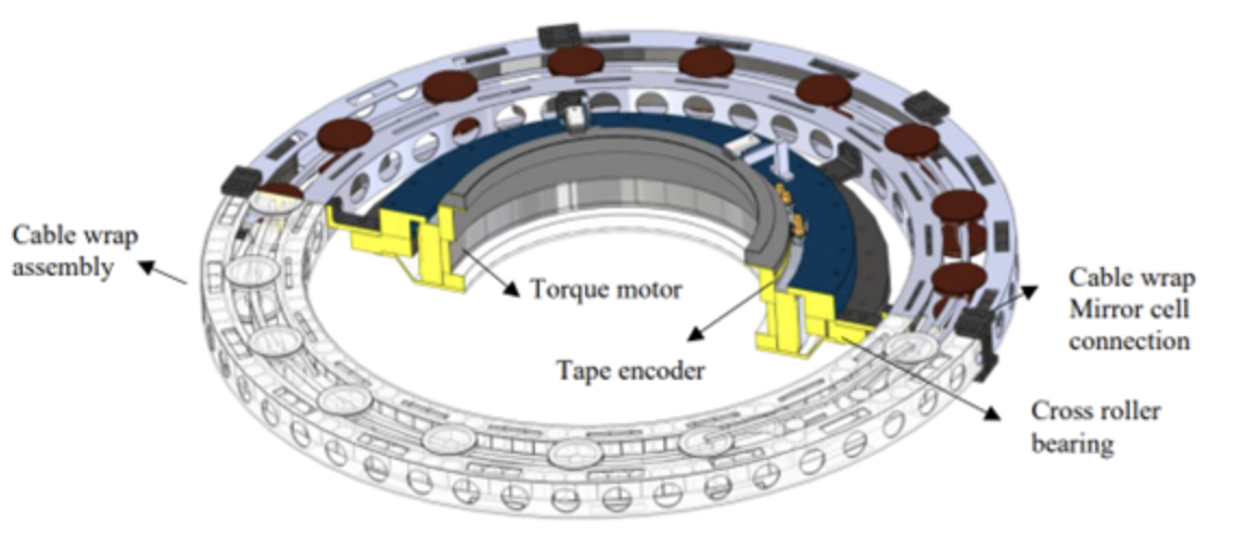
Rotator Using a field rotator that rotates the entire focal station (bottom of telescope tube) means each instrument does not need its own de-rotator so they can be lighter and less complicated (good for a low maintenance system). The rotator is fixed rigidly to the bottom of the primary mirror cell and has a hole in the centre to allow the optical beam to pass through. It is 1.2m in diameter and consists of a large direct drive motor (torque motor), a slew bearing, optical encoders for position and an externally mounted cable wrap. The rotator will be able to rotate +/-270 degrees allowing for long periods of observation tracking without needing to ‘unwrap’ the cables within the cable wrap. The motor rotates very slowly when tracking (at sidereal rate) so 0.25 degrees per minute will be its normal operating speed during observations, with possible faster slews which can reach 5 RPM.
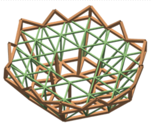
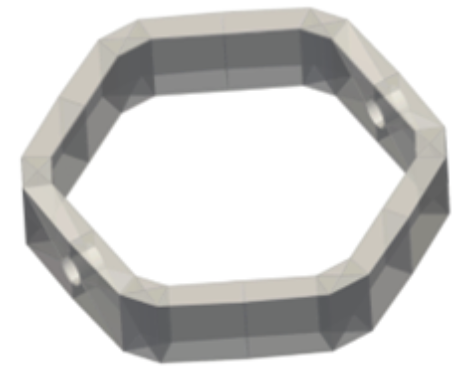
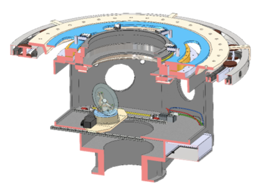
Acquisition and Guidance box (A&G box) The A&G box is a steel hexagonal structure mounted to the bottom of the rotator. Instrumentation is fixed to each of the flat outer faces with a single ‘straight through’ instrument on the bottom face. This allows 7 instruments total although the Wave front sensor will likely occupy one of the side ports. The autoguider is mounted to the bottom face and receives the optical path from the M2 via a small fold mirror. The total mass of the A&G box with all instruments is around 2000kg with each instrument port capable of supporting 120kg.